Linear driver for diving flashlight DV-S9 Led Open Source Hardware.
Introduction.
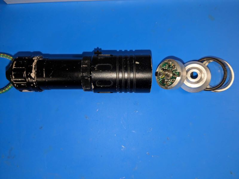
In this article, a design for a driver for a commercial Ultrafire DV-S9 diving light LED flashlight will be presented. Many clones of this flashlight can be found online at very affordable prices. It is a widely used flashlight in spearfishing, this torch is functional but with a several problems that will be explained later.
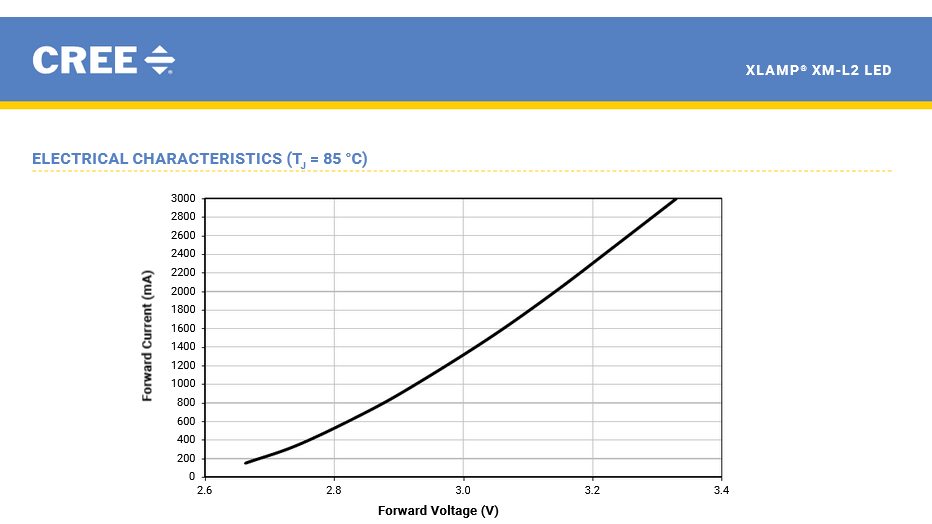
This flashlight is powered by a lithium-ion battery either 18650 or 2320, and uses a Cree XM-L2 type LED. Based on the electrical characteristics of the XM-L2,voltages between 3V and 3.4V are needed for currents between 1.5A and 3A. This voltage must be supplied from the batteries, but the voltage provided by lithium-ion batteries ranges from 2.5V to 4.2V. These flashlights use a driver to maintain constant current, typically uses a step-down driver that reduces the battery voltage to the necessary level to supply the required current. Using a step-down driver, a small percentage of battery energy cannot be utilized, as if the battery voltage is lower than the LED voltage, it cannot been illuminated. These drivers can be of the linear type, simpler, or of the switched type, which requires a more complex circuit.
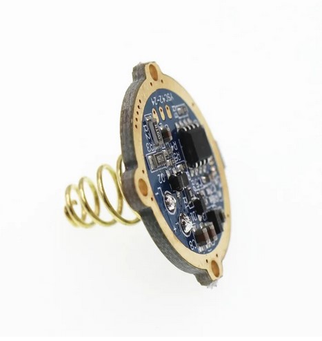
The stock flashlight is provided of a linear driver based on the AMC7136 integrated circuit, which controls three SOT23 transistors and achieves current control through an Attiny13 microcontroller by activating the regulator via a PWM signal. According to my measurements, the driver can provide a maximum current of 1.5 A and has a standby consumption of 10 mA. To activate the flashlight, it uses a Hall effect switch. The standby current is produce by the Hall effect switch and the microcontroller is relatively high, and causes the battery discharge if it is not disconnected when not in use. Additionally, under certain circumstances, electrolysis can occur in the aluminum casing.
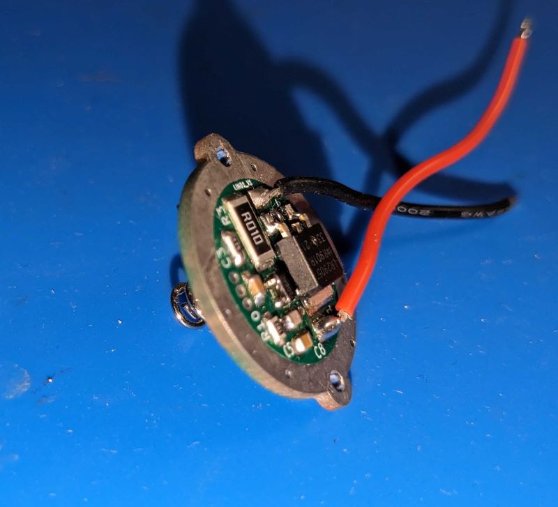
The objective is to design a low-cost driver to replace the original one, allowing current regulation between 1A and 3A without the need for a microcontroller to decrease the standby current.
Driver specifications.
The driver design has the following characteristics:
- Linear type regulator.
- Adjustable current up to 3A.
- Input voltage from 3V to 4.2V.
- Standby current of 4mA.
The block diagram of the proposed design is as follows:
The block diagram of the proposed design is as follows:
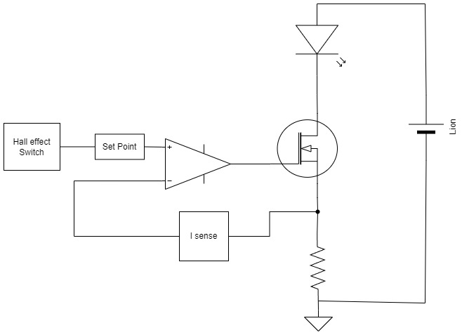
Basically, the driver design utilizes a linear regulator implemented with an operational amplifier and a MOSFET transistor to supply the required intensity to the LED. The operational amplifier is fed back with a current meter to control the output intensity on the LED and is controlled by a Hall effect sensor
Schematics.
The schematic used to implement the design is the following:

This schematic can be downloaded here: Esquema
Power supply
To power the driver, a Li-ion 18650 battery is used, which can supply between 2.5V and 4.2V, the XM-L LED requires voltages between 3V and 3.4V. Therefore, a voltage range between 3V and 4.2V will be designed. Components will be selected for a maximum voltage of 4.2V, and a 3V LDO model HT3170 is used power the control part.
Current Sensor
A 10mΩ resistor is used as the current sensor, along with an amplifier to raise the measurement voltage. A small resistor is used so that its voltage drop does not limit the LED’s supply voltage, allowing the flashlight to be powered with only 3V. For the amplifier implementation, a precision and low-offset OPAMP like the SGM8511 has been chosen.
Linear Regulator
The circuit uses a typical linear regulator with a MOSFET and an OPAMP, fed back with the current sensor to control the intensity passing through the LED based on the input voltage. For the regulator implementation, the same OPAMP used for the current sensor is chosen, along with the IRLR2905 MOSFET with very low Ron and a low Vgs voltage, enabling the flashlight to be used with an input voltage as low as 3V.
Switch
The switch controls the distance between a magnet and a S49E Hall effect sensor. To activate the flashlight, the output of the Hall effect sensor is compared with the measured voltage value when the switch is in the middle position of its travel, which is approximately 1.72V. To implement the comparator, an OPAMP of the same model used in the rest of the driver and a transistor are used to eliminate the command from the linear regulator.
PCB
A two-sided PCB has been designed to fit into the commercial flashlight casing and be easily replaceable. Considerations have been made for the permissible track currents and EMI control rules to ensure reliable current measurement with a small current measuring resistor.
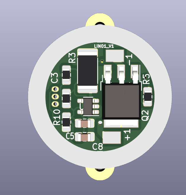
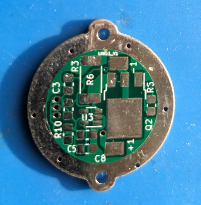
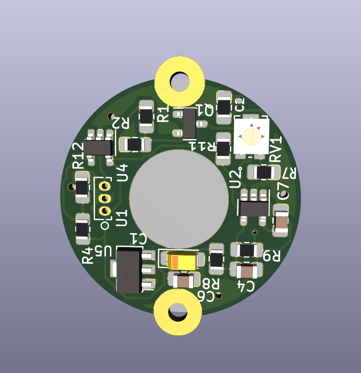
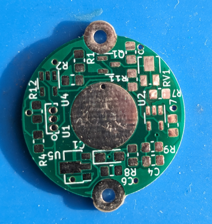
The assembled PCB looks as follows:
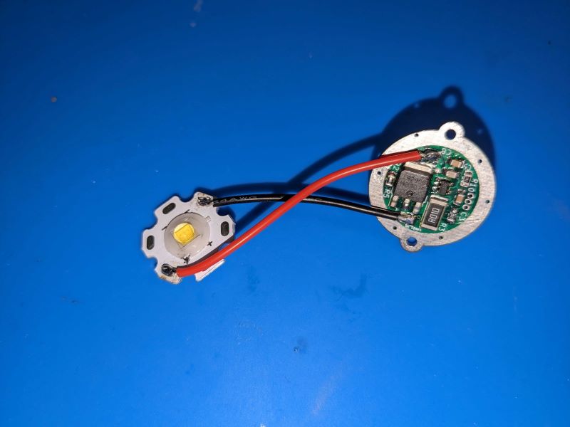
In the Github repository, includes all the manufacturing Gerber files generated for the PCB manufacturer JLCPCB, but they are compatible with most PCB manufacturing houses.
BOM.
The bill of required materials is as follows; includes the LCSC component codes.
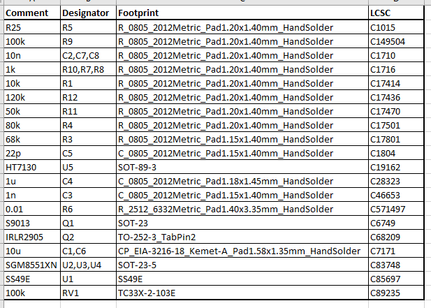
At the moment what this post is written, the price of the components for manufacturing 10 units on the LCSC website is $49.75, therefore the component cost per unit would be about $4.975/unit.
Measurements.
The following measurements have been taken:
Firstly, the standby intensity is measured with the Hall effect switch deactivated.
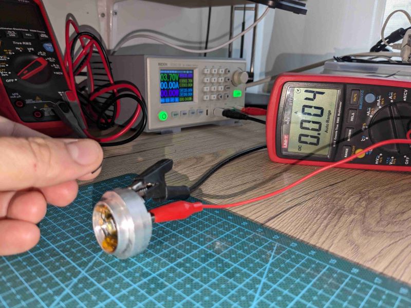
We can see that the stand by current is basically that of the Hall effect sensor, totaling 4mA.
Then, the Hall effect sensor is activated, and the current can be measured with the potentiometer adjusted to 2 A.
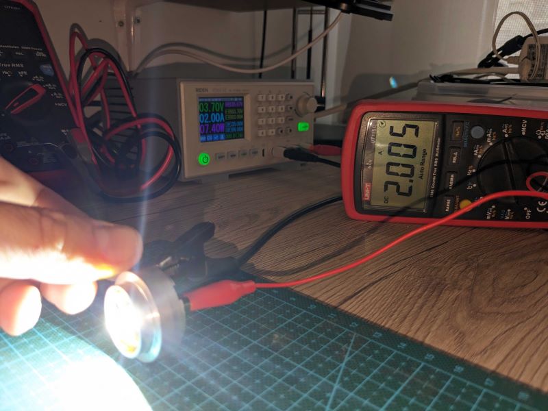
The current measured from the voltage across the 10 milliohm resistor with the oscilloscope is as follows:
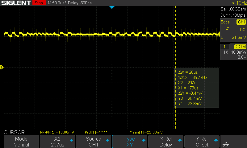
An intensity of 2A generates a voltage of approximately 20mV across the resistor. We can see that the ripple of the intensity is small; in no case does it pass through 0.
Measurement of efficiency and operating voltage.
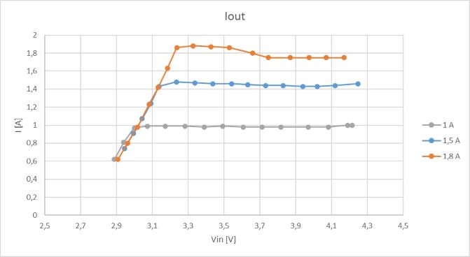
In order to obtain the driver efficiency, measurements have been taken by varying the input voltage between 2.9 V and 4.2 V, measuring both the input voltage and current, as well as the output voltage and current.
The current as a function of input voltage:
The efficiency as a function of input voltage:
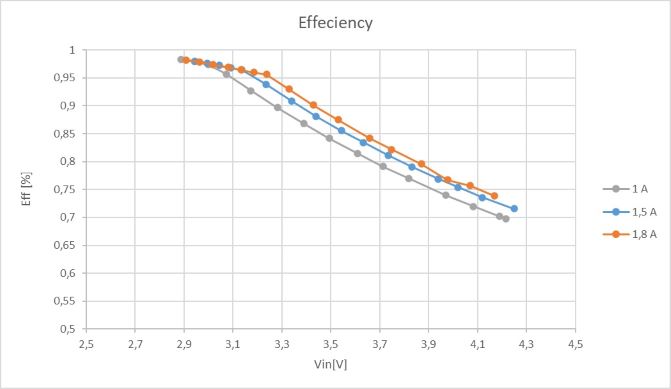
We can see that the flashlight is usable from 3 V with an intensity of 1 A and an efficiency of 98% up to 4.2 V with a minimum efficiency of 70%.
Beam comparison.
The comparison between the beam of a standard 1.5 A flashlight and a beam with the flashlight with the driver designed regulated at 2 A is as follows:
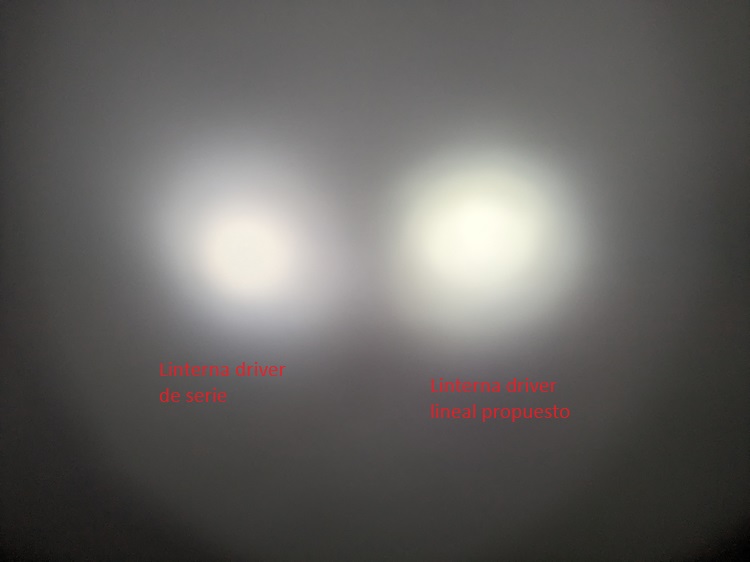
It can be seen that the designed driver illuminates slightly more than the original driver.
Design files and License.
All the documentation for the design, including the KiCad PCB project, manufacturing documents, schematic, and bill of materials, can be found in the following GitHub repository:
https://github.com/luicer/Linear-Flashlight-DV-S9-Driver
This design is open source hardware under the permissive CERN OHL-p V2 license.
